Every smart home system, security camera, conference room display, and network connection in your building depends on one thing: the cables running behind your walls. Understanding what is structured...
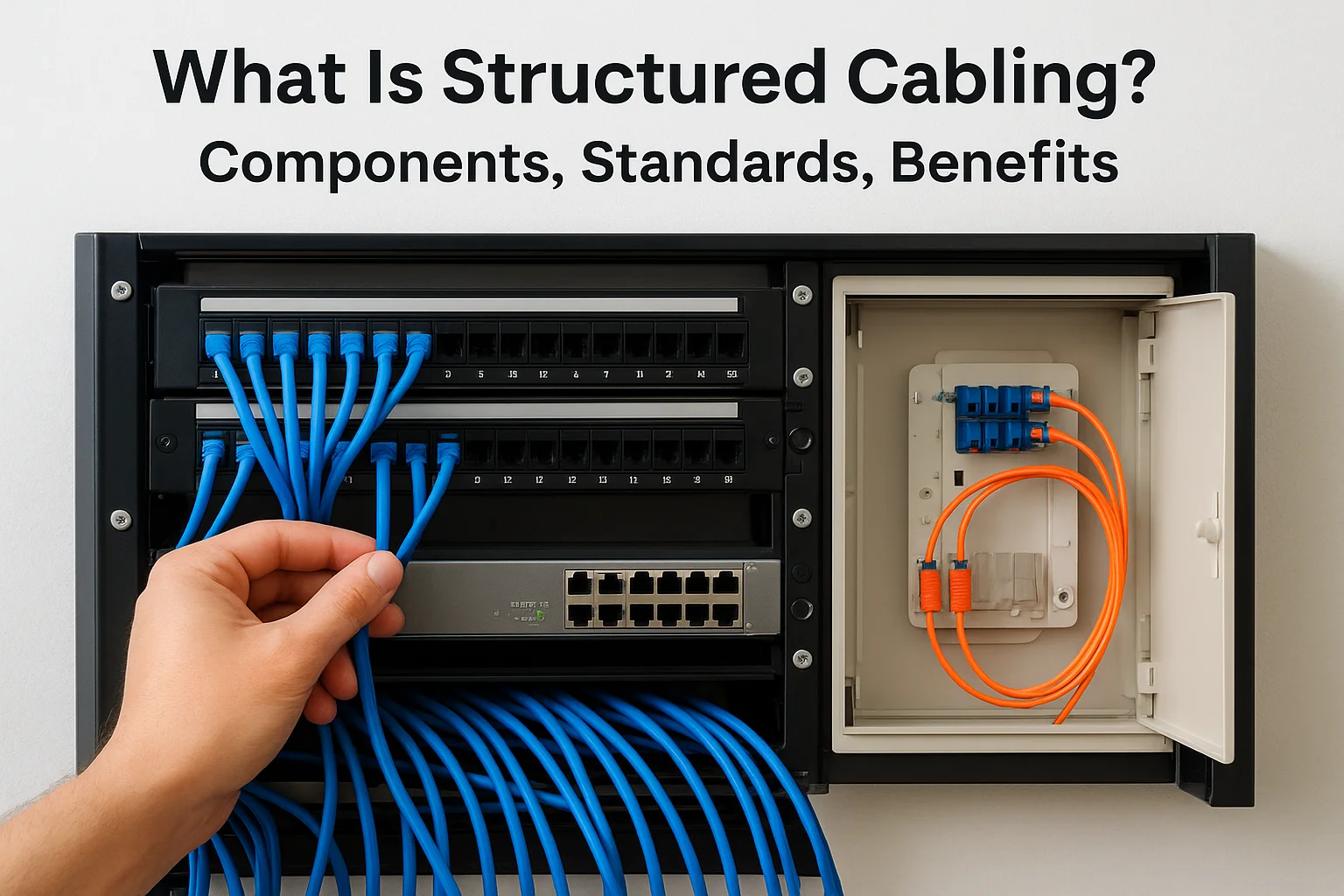
What Is Structured Cabling? Components, Standards, Benefits
Every smart home system, security camera, conference room display, and network connection in your building depends on one thing: the cables running behind your walls. Understanding what is structured cabling gives you the foundation to make informed decisions about your property's technology infrastructure, whether you're building new, renovating, or troubleshooting persistent connectivity issues. At Treasure Valley Solutions, we've designed and installed cabling systems for homes and businesses across Idaho since 2014, and we've seen firsthand how proper cabling infrastructure separates reliable technology from frustrating headaches.
Structured cabling is a standardized approach to organizing the cables, connectors, and hardware that carry data and communications throughout a building. Unlike the tangled mess of point-to-point connections that plague many older installations, a structured system follows established standards and uses six defined components to create an organized, scalable network backbone. This matters because your smart lighting, surveillance cameras, audio systems, and business networks all compete for bandwidth, and they all need a clean path from source to destination.
This guide breaks down structured cabling into practical terms. You'll learn exactly what each of the six subsystems does, which standards govern installation quality, and why businesses and homeowners increasingly choose structured cabling over cheaper alternatives. By the end, you'll know what to look for when evaluating your current setup or planning a new installation.
Why structured cabling matters
You might question whether structured cabling justifies its upfront investment, especially when cheaper alternatives seem to work initially. The reality is that your building's cabling infrastructure affects every technology decision you'll make for the next 15 to 20 years. Structured cabling creates a stable foundation that adapts as your needs change, while point-to-point wiring locks you into outdated configurations that cost more to maintain and eventually replace. When you install security cameras today and add smart building controls next year, structured cabling lets both systems coexist without interference or expensive rewiring projects.
Future-proofing your technology investments
Technology standards evolve faster than most building components. Your business might run on gigabit ethernet today, but 10-gigabit and 25-gigabit standards are already becoming mainstream in commercial spaces. Structured cabling anticipates these changes by using standardized pathways and termination points that support upgrades without tearing out walls. When you need to replace a cable run or add capacity, you simply pull new cables through existing pathways instead of cutting into drywall or dropping ceiling tiles.
Property managers see this benefit most clearly when tenants request technology upgrades. A properly installed structured system lets you add data drops, relocate workstations, or expand network coverage in hours rather than days. Your cabling becomes an asset that increases property value instead of a liability that requires constant patching and workarounds.
Structured cabling typically supports three to four generations of active equipment before the physical infrastructure needs replacement, making it one of the longest-lived building systems you'll install.
Cost savings over the building's lifetime
The math on structured cabling favors long-term thinking. You'll spend more during initial installation, but maintenance costs drop dramatically because technicians don't waste time tracing mystery cables or diagnosing intermittent failures. Every cable follows a documented path to a labeled patch panel, so troubleshooting becomes methodical instead of guesswork. When a connection fails, you identify the affected cable in minutes, test it with standard tools, and replace it without disturbing other circuits.
Business owners save money on service calls and lost productivity. Your IT team or service provider can manage moves, adds, and changes without specialized knowledge of your building's unique wiring quirks. This standardization means you're not locked into one vendor who knows where everything is hidden, and you can get competitive quotes for future work because every qualified technician understands the system layout.
Reliability and performance consistency
Structured cabling eliminates the interference and signal degradation that plague unorganized installations. Proper cable management keeps power lines separated from data cables, prevents excessive bending that damages internal conductors, and maintains the correct termination distances at every connection point. These details matter because a single poorly crimped connector or cable run that violates minimum bend radius can create packet loss that slows your entire network.
You notice this reliability in daily operations. Conference room displays don't flicker mid-presentation, security camera feeds stream without stuttering, and your smart building controls respond instantly to commands. Consistent performance happens because structured cabling treats every connection with the same engineering rigor, following specifications that have been tested across millions of installations. The standards governing what is structured cabling exist precisely to prevent the random failures that waste your time and damage your reputation with clients or tenants.
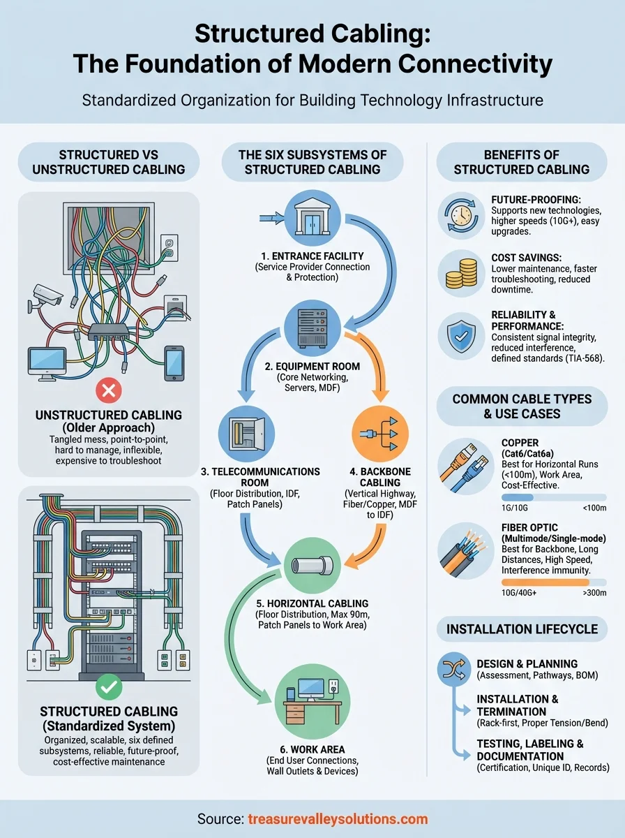
Structured vs unstructured cabling
Understanding what is structured cabling becomes clearer when you compare it to the unstructured approach most older buildings use. Unstructured cabling connects each device directly to its destination through individual cable runs, creating a web of connections that grows more complex every time you add a new system. Structured cabling organizes all connections through a central hierarchy of distribution points, pathways, and standardized components that any qualified technician can understand and modify. The difference affects everything from installation speed to your ability to troubleshoot problems five years after construction.
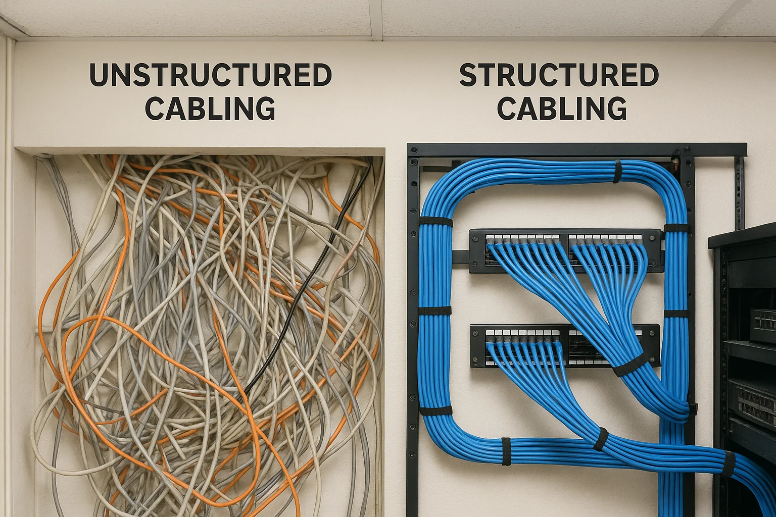
What unstructured cabling looks like in practice
Your building probably has unstructured cabling if you see cables bundled together with zip ties, running along random paths through walls and ceilings. Point-to-point installations connect each device to its specific equipment using whatever cable type the installer had available that day. One security camera might use plenum-rated cable while another uses riser-grade, and your network drops might terminate in a closet while your phone lines end in a different location entirely.
This approach creates immediate problems when you need to make changes. You can't identify which cable goes where without physically tracing it through the building, and troubleshooting becomes expensive because technicians spend hours just mapping connections before they start actual repairs. Property managers tell us they've found dead cables abandoned in walls because removing them would damage adjacent systems, and they've paid for complete rewiring jobs that could have been simple upgrades under a structured system.
How structured systems work differently
Structured cabling eliminates guesswork by routing all cables through defined pathways and termination points. Every cable run follows the same standards for length, bend radius, and separation from interference sources. Your data cables, phone lines, and building management connections all terminate at labeled patch panels in telecommunications rooms, where you can reconfigure connections simply by moving patch cables between ports.
Structured systems let you relocate a workstation or add network capacity by changing patch panel connections instead of pulling new cables through walls, reducing typical change orders from days to hours.
You gain flexibility because the physical cabling stays permanent while active equipment connects at designated distribution points. When wireless access points require upgrades, you unplug the old units and connect new ones to existing structured cable runs. This separation between permanent infrastructure and temporary equipment lets your technology evolve without touching the cables behind your walls.
The six subsystems of structured cabling
When you explore what is structured cabling in detail, you discover that every system divides into six distinct subsystems that work together as a unified infrastructure. Each subsystem serves a specific purpose in the signal path from outside your building to individual workstations, and understanding these components helps you identify where problems occur and where to invest for maximum performance. These subsystems follow the same organizational logic whether you're installing cables in a three-story office building or a 50,000-square-foot warehouse.
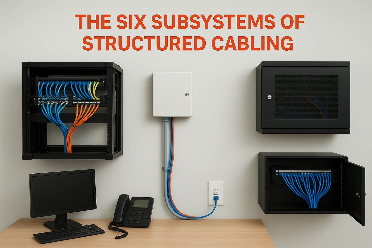
Entry point and equipment locations
Your structured cabling starts where service providers connect to your building. The entrance facility brings outside cables into your property through protected conduits and provides the demarcation point between your infrastructure and external networks. This subsystem includes the hardware that protects your internal systems from power surges and lightning strikes that travel along incoming cables.
The equipment room houses your core networking gear, servers, and primary telecommunications equipment. You'll find your main distribution frame here, along with the backbone connections that feed every telecommunications room throughout your building. Larger properties might have multiple equipment rooms on different floors, but they all connect through the backbone cabling subsystem.
Telecommunications rooms act as distribution hubs on each floor or building section. These spaces contain patch panels, switches, and the hardware that connects backbone cabling to horizontal runs serving individual work areas. Your telecommunications room might be a dedicated closet in an office building or a locked cabinet in a retail space, but it always provides the centralized access point for managing connections on that floor.
Backbone and horizontal distribution
Backbone cabling creates the vertical highway between your equipment room and telecommunications rooms. These cables carry the highest data volumes in your infrastructure and typically use fiber optic or high-grade copper conductors rated for longer distances than standard ethernet. Property managers appreciate that backbone cables rarely need replacement because they're oversized during initial installation to handle future capacity increases.
Horizontal cabling runs from telecommunications room patch panels to individual wall outlets or connection points in work areas. These cables follow strict length limits (typically 90 meters for permanent cabling) and must maintain proper separation from power sources and other interference. You see horizontal cabling when you plug devices into wall jacks, even though the cables themselves stay hidden in walls, ceilings, or raised floors.
The horizontal cabling subsystem accounts for approximately 50% of structured cabling installation costs but provides the flexibility that makes the entire system valuable for daily operations.
End user connections
The work area subsystem includes everything from wall outlets to the cables connecting your computers, phones, and other devices. This represents the only part of structured cabling that building occupants interact with directly, and it's where you plug in patch cables to activate connections. Your work area components need the most frequent replacement because they experience physical wear from connecting and disconnecting devices, but the standardized connectors make replacements simple and inexpensive.
Common structured cabling components and hardware
The physical components that define what is structured cabling include standardized hardware pieces that connect, protect, and organize your cables throughout the building. You'll encounter these same components whether you're installing a system in a small office or a multi-building campus, and understanding each piece's function helps you evaluate installation quality and plan future upgrades. Every component follows industry specifications for dimensions and performance, which means you can replace failed parts from any manufacturer that follows the same standards.
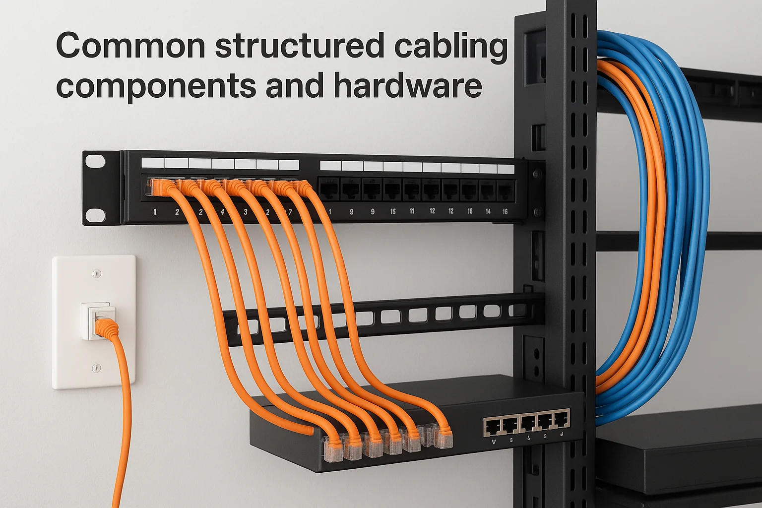
Patch panels and distribution frames
Patch panels serve as the central termination point where your permanent cabling meets flexible patch cables. These rectangular panels mount in equipment racks and provide numbered ports that correspond to specific cable runs throughout your building. You create connections by running short patch cables between patch panel ports and your active network equipment, making reconfiguration as simple as unplugging one cable and moving it to a different port.
Distribution frames organize larger volumes of connections in equipment rooms and telecommunications closets. Your main distribution frame (MDF) acts as the central hub for all backbone cabling, while intermediate distribution frames (IDFs) handle connections on individual floors or building sections. These frames let technicians manage hundreds of connections in an organized grid that makes troubleshooting and changes straightforward instead of chaotic.
Cable connectors and jacks
RJ45 connectors terminate ethernet cables at both ends of every connection. You'll see these eight-pin modular connectors on patch cables in your office and inside wall plates where horizontal cabling terminates. Quality connectors maintain proper wire pair spacing to preserve signal integrity, and they snap firmly into jacks to prevent accidental disconnections during normal use.
Keystone jacks mount in wall plates and patch panels to accept RJ45 connections. These modular components let you customize each outlet location by combining data, phone, and other connection types in a single faceplate. Technicians appreciate that keystone jacks follow tool-free termination methods that speed installation and reduce errors compared to older punch-down connectors.
Professional installations use color-coded jacks and patch cables to identify different network types or VLANs at a glance, reducing configuration errors and simplifying troubleshooting.
Racks, cabinets, and cable management
Equipment racks provide standardized mounting points for patch panels, switches, and cable management hardware. These 19-inch wide frames follow universal spacing measurements that let you mix equipment from different manufacturers in the same installation. Your telecommunications room needs adequate rack space to accommodate current equipment plus 30% expansion capacity for future growth.
Cable management accessories keep your installation organized and protect cables from damage. Horizontal cable managers mount between patch panels to guide patch cables in neat bundles, while vertical managers run along rack sides to route cables between different equipment heights. Proper cable management prevents the tangled mess that makes future changes expensive and maintains proper airflow around heat-generating network equipment.
Cable types and performance basics
The cables you choose for your structured system directly affect network performance, upgrade costs, and how long your installation remains relevant. Copper and fiber optic cables each serve specific roles in what is structured cabling, and understanding their capabilities helps you make informed decisions about where to invest in higher-grade materials. Your horizontal cabling might use copper for most connections while backbone runs benefit from fiber, and knowing the performance differences prevents bottlenecks that limit your entire network.

Copper cable categories and bandwidth
Copper ethernet cables come in numbered categories that indicate their maximum bandwidth and transmission distance. Cat5e cable handles gigabit speeds up to 100 meters and remains the minimum acceptable standard for new installations, while Cat6 cable supports 10-gigabit speeds over shorter distances and provides better protection against interference. You'll pay 15 to 25% more for Cat6, but it extends your system's useful life by supporting faster equipment as you upgrade switches and access points.
Cat6a cable represents the current high-end choice for copper installations. This augmented category handles 10-gigabit speeds across the full 100-meter horizontal distance and includes enhanced shielding that reduces crosstalk between adjacent cables. Data centers and buildings with high-density cabling prefer Cat6a because it eliminates speed degradation in bundled cable runs, though the thicker diameter makes it harder to install in congested pathways.
Cat6a installations typically cost 40% more than Cat6 during initial construction but eliminate the need for rewiring when you upgrade to 10-gigabit network equipment.
Fiber optic cable advantages
Fiber optic cables transmit data as light pulses through glass or plastic strands, achieving speeds and distances that copper cannot match. Multimode fiber handles 10-gigabit to 40-gigabit speeds across 300 to 550 meters and works well for backbone connections between telecommunications rooms. Single-mode fiber extends those distances to several kilometers and supports the highest bandwidth requirements, making it the standard choice for connections between buildings or to service provider entry points.
Your structured cabling benefits from fiber's immunity to electromagnetic interference and superior security characteristics. Copper cables act as antennas that pick up interference from nearby power lines and emit signals that sophisticated equipment can intercept, while fiber optic connections remain unaffected by electrical noise and impossible to tap without physically breaking the cable.
When to choose each cable type
Budget-conscious projects use Cat6 copper for horizontal runs to workstations and endpoints while installing multimode fiber for backbone connections between telecommunications rooms. This hybrid approach balances performance with installation costs because most devices still connect through copper ethernet ports. You'll want fiber for any connection covering more than 100 meters, linking separate buildings, or supporting extremely high bandwidth requirements like 4K video distribution.
Key standards and what they actually control
Standards define the technical specifications and installation practices that separate professional structured cabling from amateur work. ANSI/TIA-568 remains the primary standard governing what is structured cabling in North America, while ISO/IEC 11801 provides international specifications that largely align with TIA requirements. These documents specify everything from minimum bend radius and maximum pulling tension to connector pin assignments and testing procedures, creating a universal language that lets technicians in different cities or countries understand your installation immediately. You benefit because any qualified contractor can troubleshoot, expand, or modify your system without learning proprietary methods.
What TIA-568 actually specifies
The TIA-568 standard family controls the physical installation requirements that determine whether your cabling performs reliably. TIA-568.0 establishes general requirements for all commercial building cabling, including the six-subsystem architecture that organizes modern installations. TIA-568.1 through TIA-568.4 provide detailed specifications for copper cabling, fiber optic installations, and specific environments like data centers or industrial facilities.
Your installer follows these standards when determining cable lengths between distribution points, maintaining proper separation distances from electrical interference sources, and selecting appropriate fire ratings for different building spaces. The standard specifies that horizontal cable runs cannot exceed 90 meters of permanent cabling, with an additional 10 meters allowed for patch cables at both ends. These limits prevent signal degradation that would cause packet loss and reduced network speeds.
Professional installations following TIA-568 standards typically achieve 99.9% pass rates on certification testing, while non-compliant installations often require expensive remediation to meet performance requirements.
Testing and certification requirements
Standards organizations define the test parameters and acceptance criteria that verify your installation meets performance specifications. You test each cable run using time-domain reflectometry to measure length and identify defects, plus frequency-domain testing that validates bandwidth capabilities across the entire spectrum your cable category supports. These tests catch installation errors like reversed wire pairs, excessive untwisting at termination points, or damaged cables before they cause network problems.
Your structured cabling warranty depends on passing these certification tests. Manufacturer warranties covering 15 to 25 years require documented proof that your installation meets all applicable standards, and many property insurance policies specify minimum cabling standards for buildings with valuable technology assets. Without proper testing documentation, you lose these protections and face higher costs when troubleshooting connectivity issues.
How structured cabling gets designed and installed
Professional structured cabling installation follows a systematic process that transforms your building's empty walls and ceilings into an organized network infrastructure. Design work begins weeks before installers arrive at your property, and the process involves multiple stages that each address specific technical requirements and coordination challenges. Your project timeline typically spans two to six weeks depending on building size, with design consuming roughly 30% of that schedule and physical installation taking the remainder. Understanding this workflow helps you plan construction schedules, coordinate with other trades, and set realistic expectations for when your systems become operational.
Site assessment and planning phase
Your installer begins by surveying the property to identify optimal telecommunications room locations, cable pathway routes, and potential obstacles that affect installation difficulty. This assessment maps where your equipment rooms will connect to telecommunications closets, identifies the most efficient paths through walls and ceilings, and locates electrical interference sources that require minimum separation distances from data cables. Commercial buildings need floor plans showing structural elements, HVAC ductwork, and electrical conduit so designers can plan pathways that avoid conflicts with other building systems.
The planning phase produces detailed documentation that specifies cable types, quantities, and termination locations for every connection point in your building. You receive pathway drawings showing horizontal and backbone cable routes, equipment room layouts indicating rack positions and power requirements, and a comprehensive bill of materials listing every component from patch panels to mounting hardware. This documentation becomes the blueprint that guides installers and provides the permanent record of your infrastructure for future maintenance and modifications.
Experienced designers typically allocate 20 to 30% spare capacity in telecommunications rooms and backbone pathways to accommodate future expansion without major renovations.
Installation sequence and workflow
Installers start by placing telecommunications equipment racks and mounting patch panels before running any cables. This rack-first approach ensures that termination hardware is properly positioned and secured, preventing the need to adjust or relocate equipment after cables are already pulled. Your telecommunications rooms receive proper grounding systems and dedicated electrical circuits that power network equipment without overloading shared circuits or creating interference with data transmission.
Cable installation progresses systematically through backbone runs first, then horizontal cabling to individual connection points. Installers pull cables through designated pathways using measured tension that prevents conductor damage, maintain minimum bend radius specifications at every turn, and secure cables at regular intervals using approved mounting hardware. Commercial installations often require fire-stopping at penetrations between floors or fire-rated zones, where specialized materials seal openings while allowing cables to pass through safely.
Testing, labeling, and documentation
Your structured cabling installation isn't complete until every cable passes performance testing, receives proper labels, and gets documented in detailed records that future technicians can reference. These final steps transform a collection of physical cables into a managed infrastructure asset that delivers consistent performance and simplifies troubleshooting throughout your building's lifetime. You might view testing and documentation as administrative overhead, but these activities protect your investment by proving compliance with warranty requirements and creating the reference materials that make changes fast and inexpensive. Professional installers budget 15 to 20% of total project time for testing, labeling, and documentation tasks that verify every aspect of what is structured cabling before handing over a completed system.
Cable testing procedures and certification
Every cable run receives comprehensive testing that measures physical characteristics and electrical performance. Wiremap tests verify that conductors connect to the correct pins at both ends, catching reversed pairs or crossed wires that would prevent communication entirely. Length measurements confirm that your horizontal runs stay within the 90-meter permanent cabling limit, while propagation delay testing identifies cables with excessive signal travel time that could cause network errors at high speeds.
Performance certification requires testing across the entire frequency range your cable category supports. Your Cat6 installation undergoes testing from 1 MHz to 250 MHz to validate return loss, insertion loss, and near-end crosstalk at every frequency step. These tests generate pass/fail results that document your installation meets TIA-568 requirements, and failed cables require remediation before you receive certification paperwork that activates manufacturer warranties. Testing equipment costs $5,000 to $15,000, which is why professional installation includes certification as part of the package rather than leaving it to building owners.
Certified installations typically achieve 99% first-test pass rates when installers follow proper termination procedures, while uncertified work often fails 30% of connections due to preventable errors.
Labeling standards and best practices
Labels applied at every termination point create the visual reference system that makes your structured cabling manageable. You label both ends of each cable run with unique identifiers that match entries in your documentation, typically combining room numbers with port sequences like "TC2-A-012" for the twelfth port in rack A of telecommunications closet 2. Wall plates receive labels indicating which patch panel port they connect to, and patch panels display port numbers that correspond to specific work area locations throughout your building.
Color coding supplements text labels by providing instant visual identification of different cable types or network segments. You might use blue cables and jacks for data connections, yellow for voice systems, and red for building management networks. This visual system lets technicians identify connection types without reading labels, reducing errors during maintenance work and helping non-technical building occupants understand which jacks serve what purposes.
Documentation requirements and maintenance records
Complete documentation packages include floor plans showing cable pathways, telecommunications room layouts with rack elevations, and spreadsheets listing every cable run with its endpoints and test results. Your records specify cable types, lengths, and installation dates for each connection, creating the baseline information you need when troubleshooting problems or planning expansions. Digital documentation stored in building management systems lets multiple stakeholders access current infrastructure maps without searching for paper drawings that may be outdated or missing.
As-built drawings capture changes made during installation that differ from original designs. Your installer documents pathway route modifications, additional cable runs not shown in original plans, and equipment room layout adjustments that occurred during construction. These updates ensure your documentation reflects actual conditions behind walls and above ceilings, preventing the disconnect between paper records and physical reality that wastes time during future projects.
Final takeaways
Understanding what is structured cabling gives you the knowledge to evaluate your current infrastructure and plan future technology investments with confidence. You've learned that structured cabling separates permanent infrastructure from temporary equipment, creating a flexible foundation that adapts as your technology needs evolve. The six-subsystem architecture, standardized components, and rigorous testing protocols distinguish professional installations from amateur work that creates long-term headaches.
Your building deserves cabling infrastructure that supports reliable performance for 15 to 20 years, and that starts with proper design and installation from experienced professionals. Whether you're constructing a new property, renovating an existing space, or troubleshooting persistent connectivity issues, structured cabling provides the organized backbone that modern homes and businesses require. Treasure Valley Solutions has designed and installed structured cabling systems for residential and commercial clients across Idaho since 2014, bringing the same attention to detail and standards compliance to every project. Contact us to discuss your cabling needs and get a clear assessment of what your property requires.